There are no items in your cart
Add More
Add More
| Item Details | Price | ||
|---|---|---|---|

{{DATE}}
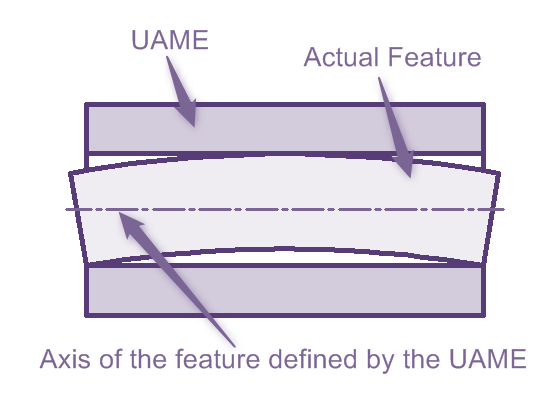
Axis of a feature is the axis of an unrelated actual mating envelope or actual minimum material envelope of a feature.
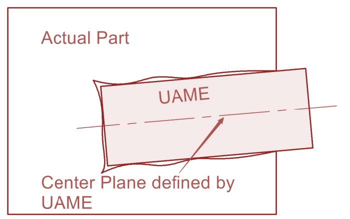
Center Plane of a Feature is the center plane of an unrelated actual mating envelope or actual minimum material envelope of a feature.
Derived Median Line is an imperfect line that passes through the center points of all cross sections of the feature. These cross sections are normal to the center plane of the unrelated actual mating envelope.
Derived Median Plane is an imperfect plane formed by the center points of all line segments bounded by the feature. These line segments are normal to the center plane of the unrelated actual mating envelope.
Modifiers communicate the additional information about the drawing or tolerancing of a part.
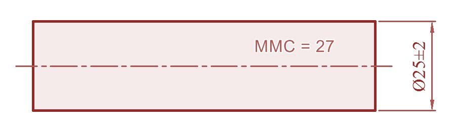
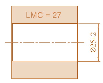
Maximum Material Condition (MMC): Maximum material condition is the condition in which a feature of size contains the maximum amount of material everywhere within the stated limits of size- for example, the largest shaft diameter or smallest hole diameter.
In simple Words, maximum material condition adds material to the part, increases the weight of the part.
Maximum Material Boundary (MMB): Maximum material boundary is the limit defined by a tolerance or combination of tolerances that exists on or outside the material of a feature(s)
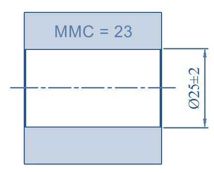
Least Material Condition (LMC): Least Material Condition is the condition in which a feature of size contains the least amount of material everywhere within the stated limits of size for example, the smallest shaft diameter or the largest hole diameter.
In simple Words, least material condition removes material from the part, decreases the weight of the part.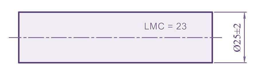
Least Material Boundary (LMB): Least material boundary is the limit defined by a tolerance or combination of tolerances that exists on or inside the material of a feature(s)
Regardless of feature size (RFS) is the term that indicates a geometric tolerance applies at any increment of size of the feature within its size tolerance. An-other way to visualize RFS is that the geometric tolerance applies at whatever size the part is produced. Every feature of size has a maximum and least material condition. Limit directions directly
specify the maximum and least material condition of feature of size.
Regardless of Material Boundary (RMB) is a condition in which a movable or variable true geometric counterpart progresses from MMB towards LMB until it makes maximum allowable contact with the extremities of a datum feature(s) to establish a datum.
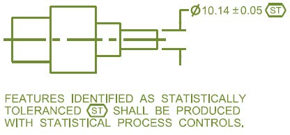
Statistical Tolerancing Symbol denotes that the dimension to tolerance to which it is applied was established by statistical methods. Features identified with statistical tolerancing symbol must be manufactured with statistical process control and must be accompanied with a note as shown. When using the staticitical tolerancing symbol the necessary statistical indices should be specified on the drawing or in a referenced document.

{{AUTHOR}}
Trainer - GD&T, TSA I Consultant I YouTuber I Blogger I Mentor I Career Coach
 Launch your Graphy