There are no items in your cart
Add More
Add More
| Item Details | Price | ||
|---|---|---|---|

Sat Aug 23, 2025
The Projected Tolerance Zone modifier changes the location of the tolerance zone on the part. It projects the tolerance so that it exists above the part. The projected tolerance zone modifier is used to assure that there will not be interference between a screw,stud,dowel dowel pin, etc. and the mating part containing a clearance hole. 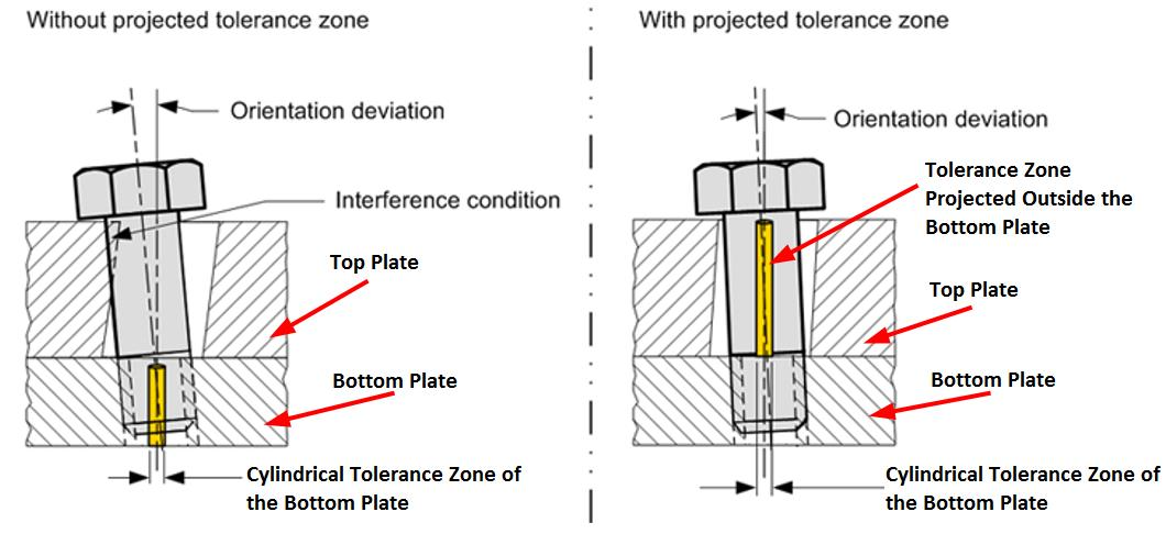
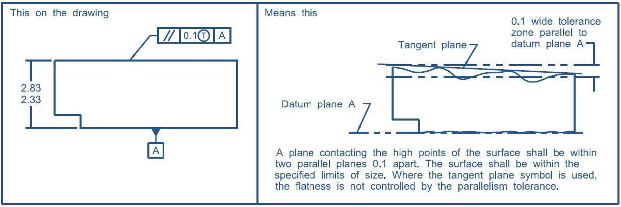
The Tangent Plane modifier denotes that only the tangent plane of the toleranced
surfaces needs to be within this tolerance zone. It means that the tolerance applies to a
plane established by the high points of the surface. The flatness error in that surface will be ignored during inspection.
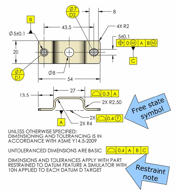
Free State is the condition of a part free of applied forces. Dimensions and tolerances
apply where parts are in the free state condition unless otherwise stated in the note. This
means that a part should not have any forces applied to it for inspection unless a restraint
note is shown. Where a restraint note is specified on drawing, the free state symbol may
be used in the geometric tolerance to unlock the part from the restraint requirement.
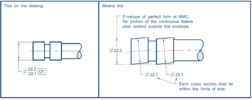
Continuous Feature Modifier symbol or the note “Continuous Feature” indicates that a
group of two or more features or feature of sizes are to be treated geometrically as a
single feature or a feature of size.
The continuous feature symbol can be used to indicate that an interrupted feature or
feature of size.
When an Independency symbol is used on a feature of size dimension, it indicates that
the size and form are independent for that feature of size dimension. Rule #1 does not
apply. In such cases perfect form at MMC or LMC is not required.
When the independency principle is used, a form tolerance such as a straightness or
flatness tolerance, should be specified to a surface of the feature of size to define its
boundary.
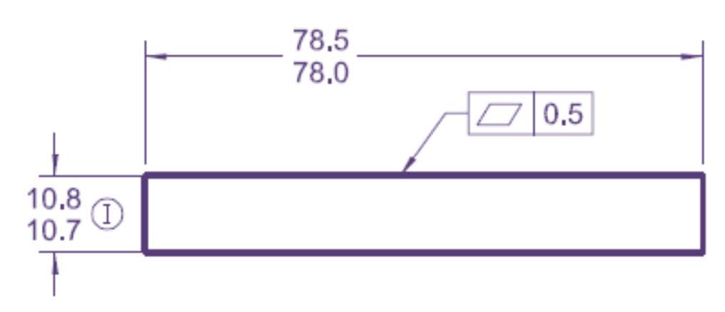
A Feature Control Frame is a rectangular box that is divided into compartments within
which geometric characteristic symbol, tolerance value, modifiers, and datum references
are placed. The compartments of a feature control are shown in figure below.
The first compartment of the feature control frame is called the geometric characteristic
portion. It contains one of the fourteen characteristic symbols.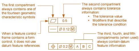
The second compartment of the feature control frame is referred to as the tolerance
portion. This portion may contain several bits of an information. For example, if the
tolerance value is preceded by a diameter symbol, the shape of the tolerance zone is a
cylinder. If a diameter symbol is not shown in front of the tolerance value, the shape of
the tolerance zone is parallel planes, parallel lines or a uniform boundary in the case of
profile. The tolerance value specified is always a total value.
When specifying a non-datum related control, the feature control frame will have two
compartments. When specifying a datum related control, the feature control frame may
have up to five compartments: the first for a geometric characteristic symbol, one for
tolerance information, and up to three additional compartments for datum references.
The third, fourth and fifth compartments of the feature control frame are referred to as
the datum reference portion of the feature control frame.
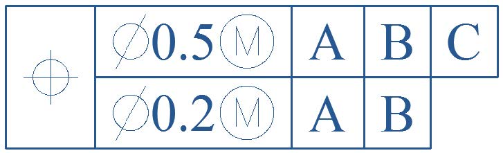
Composite Feature Control Frame is where the feature control frame has one symbol
flowed by multiple segments. The lower segment is the refinement of the control
provided by the upper segment.
Composite feature control frame is commonly used with position and profile tolerancing.

Prolotek
Trainer - GD&T, TSA I Consultant I YouTuber I Blogger I Mentor I Career Coach
 Launch your Graphy